
 Nov 04,2026
Power capacity is one of the first constraints that decides whether a thermoforming line can run at rated speed—or at all. Calculating the factory power load is not a single number; it is a structured exercise that starts with a load list, applies demand factors, accounts for motor starting, and ends with a transformer and distribution design that can carry the line without nuisance trips. This guide explains the method step by step, with tables and a commissioning checklist you can use before the machine arrives.
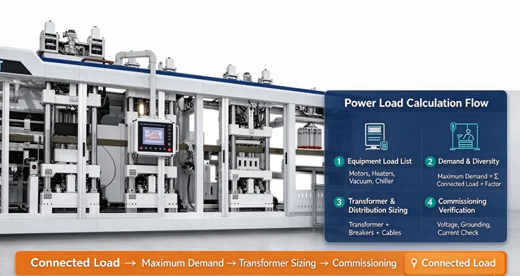
Many installation delays trace back to electrical capacity. A line may be mechanically ready, but if the transformer, distribution cabinet, or cable sizing cannot carry the connected load, commissioning stops. The cost of upgrading electrical infrastructure after the machine is on site is usually higher than planning it correctly in advance.
Two numbers matter from the start:
Connected load is always higher than maximum demand, because not every motor runs at full power at the same time. The design must be based on maximum demand, but the load list must start with connected load.
For buyers still at the factory planning stage, this calculation sits inside the broader site preparation work covered in the plastic thermoforming line factory setup guide. Power is one of several utilities that must be confirmed before the machine is built.
The load list is the foundation. It should include every piece of equipment that draws power, with its rated power, voltage, phase, and whether it runs continuously or intermittently.
A typical thermoforming line load list includes:
| Equipment | Typical Load Type | Notes |
|---|---|---|
| Thermoforming machine main drive | Motor, continuous | Servo or standard motor depending on model |
| Heating zones | Resistive, continuous during production | Usually the largest single load |
| Forming station servo motors | Motor, intermittent | Peak during forming cycle |
| Punching and cutting station | Motor or hydraulic, intermittent | Cycle-dependent |
| Stacking and manipulator | Motor, intermittent | May be optional |
| Vacuum pump | Motor, continuous | Load varies with vacuum demand |
| Chiller | Compressor and pump, continuous | Significant if water-cooled |
| Air compressor | Motor, intermittent duty | Load depends on storage and demand |
| Sheet extruder (if inline) | Motor and heating, continuous | Separate large load |
| Control system and lighting | Small, continuous | Often grouped |
For each item, record:
The equipment supplier should provide a connected load schedule for the specific configuration. Buyers should request this document before finalizing the electrical plan, not after.
Not all connected load is drawn at the same time. Demand factors and diversity factors convert connected load into a realistic maximum demand.
A practical approach for a thermoforming line:
| Load Group | Consideration | Planning Note |
|---|---|---|
| Heating zones | Usually near full load during production | Apply a high demand factor; heating is the dominant continuous load |
| Main drive and servo motors | Intermittent peaks | Apply a moderate demand factor; check peak coincidence |
| Vacuum and compressed air | Varies with cycle | Apply a moderate demand factor; confirm compressor duty cycle |
| Chiller | Continuous during production | Apply a high demand factor if water-cooled |
| Auxiliary and control | Small | Apply a high factor; the total is usually minor |
The exact factors depend on the specific line configuration, cycle time, and operating pattern. There is no universal number that applies to every plant. Buyers should ask the equipment supplier for the recommended demand factors for the specific model, and verify with the electrical engineer designing the distribution system.
A simple maximum demand estimate:
Maximum demand ≈ Σ (connected load of each group × demand factor of that group)
This estimate is the basis for transformer and cable sizing, not the connected load total.
Motor starting current can be several times the running current. If the distribution system is sized only for running load, starting a large motor may cause voltage dips, nuisance trips, or damage to sensitive controls.
Key points:
For the thermoforming line, the largest starting currents usually come from:
The distribution design should confirm that starting the largest motor while other loads are running does not cause an unacceptable voltage dip. The acceptable dip depends on the local grid and the sensitivity of the control system; the electrical engineer should confirm the limit for the specific site.
Transformer sizing follows from maximum demand, with margin for future expansion and for starting conditions.
A practical sequence:
| Sizing Factor | What It Covers | Planning Note |
|---|---|---|
| Maximum demand | Normal running load | Base for transformer rating |
| Future margin | Additional equipment or higher output | Typically a percentage added to maximum demand |
| Starting current | Largest motor start | May require a larger transformer or reduced starting method |
| Power factor | Reactive power | May require correction to avoid utility penalties |
Power factor correction may be required if the utility applies a reactive power charge. Capacitor banks or active correction can be specified as part of the distribution design.
For lines that include an inline sheet extruder, the extruder is often a separate large load and should be included in the same calculation. The PP/PS sheet extruder page shows available configurations; the Sinoplast team can confirm the connected load for a specific model.
A single main breaker for the whole line is not practical. The distribution should be divided into circuits that match the load groups and allow safe isolation during maintenance.
A typical division:
| Circuit Group | Typical Loads | Purpose |
|---|---|---|
| Heating | Heating zones | Separate circuit for temperature control and isolation |
| Main drive and servo | Forming, punching, cutting | Separate circuit for motor protection |
| Vacuum and compressed air | Vacuum pump, air compressor | Separate circuit for intermittent duty |
| Cooling | Chiller, pumps | Separate circuit for continuous duty |
| Control and instrumentation | PLC, sensors, HMI | Separate circuit with clean power if required |
| Lighting and auxiliary | Workshop lighting, small tools | Separate circuit |
Each circuit should have its own protection, cable sizing, and isolation point. Labeling at the distribution cabinet should match the layout drawing so that maintenance can isolate the correct circuit without guesswork.
The machine's electrical design must match the site supply. Common requirements:
Buyers should provide the supplier with the local voltage, frequency, and phase before production begins. If special design is required, the price and lead time may differ.
The calculation is only as good as the verification. At commissioning, confirm that the installed system matches the design and that the line can run at rated conditions without electrical issues.
Electrical commissioning checklist:
If any item fails, correct it before production begins. Electrical faults discovered during production are more expensive to fix and can damage equipment. For installation and commissioning support, review the service page or contact the team through Contact Us.
Each of these is avoidable with a structured load list and a commissioning checklist.
The connected load depends on machine size, number of heating zones, whether an extruder is included, and auxiliary equipment. Buyers should request a connected load schedule from the equipment supplier for the specific configuration and calculate maximum demand using demand factors. There is no single number that applies to every line.
Connected load is the sum of the rated power of all installed equipment. Maximum demand is the highest power the line actually draws in normal operation, after demand factors are applied. Transformer and cable sizing should be based on maximum demand, not connected load.
Motor starting current can be several times the running current. If the transformer or distribution system is sized only for running load, starting a large motor may cause voltage dips, nuisance trips, or damage to sensitive controls. The design should confirm that starting the largest motor does not cause an unacceptable voltage dip.
A voltage stabilizer may be required in areas with unstable grid supply, especially where heating and control electronics are sensitive to voltage variation. The need depends on the local grid quality and the machine's electrical design. Buyers should confirm with the supplier and the electrical engineer.
Three-phase 380V/50Hz is standard for many configurations. Other voltages can be designed on request. Buyers should confirm the local supply and any need for a voltage stabilizer before ordering.
Divide the distribution into circuits that match the load groups: heating, main drive and servo, vacuum and compressed air, cooling, control and instrumentation, and lighting and auxiliary. Each circuit should have its own protection, cable sizing, and isolation point, labeled to match the layout drawing.
Confirm voltage and phase, transformer capacity and tap setting, breaker ratings, cable sizing, grounding resistance, lightning protection, heating zone stability, motor current, vacuum pump and compressor starting, chiller operation, emergency stop, control system communication, and power factor or harmonic levels if required by the utility.
Power load calculation is a structured exercise, not a single number. Start with the equipment load list, apply demand and diversity factors to estimate maximum demand, account for motor starting current, size the transformer and distribution with margin, divide the distribution into circuits that match the load groups, and verify at commissioning. The most common mistakes are sizing for connected load instead of maximum demand, ignoring starting current, and skipping commissioning verification.
For lines where the electrical configuration or connected load is a planning constraint, review the available plastic thermoforming machine and plastic cup making machine configurations, or discuss the site supply with the Sinoplast engineering team through contact us. The broader site preparation process is covered in the plastic thermoforming line factory setup guide.
We are a professional plastic machinery provider in China.