You have selected your thermoforming machine. The specifications look right, the price fits your budget, and delivery timelines align with your production launch. But when the line is installed and running, problems emerge: cycle times slow down, parts warp as they cool, or the machine stalls mid-cycle due to insufficient air pressure.
The issue is rarely the thermoforming machine itself. More often, it is the auxiliary equipment — air compressors, chillers, and storage tanks — that were undersized or overlooked. These supporting components are not optional accessories; they are essential to consistent production.
This guide explains how to size each piece of auxiliary equipment correctly, so your thermoforming line runs at its rated speed without unexpected interruptions.
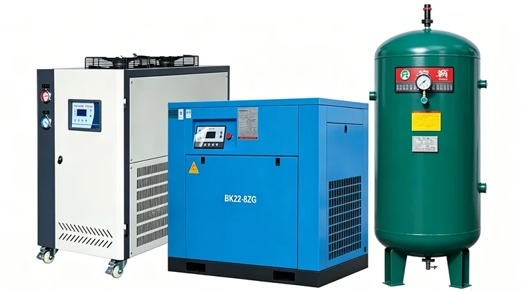
Thermoforming machines operate through positive and negative pressure, requiring large volumes of compressed air. Molds generate significant heat during production, which must be removed continuously to maintain cycle times and part quality. If any supporting system is undersized, the entire line suffers.
The consequences of undersized auxiliary equipment:
| Symptom | Likely Cause | Impact on Production |
|---|---|---|
| Slow forming cycles | Insufficient air pressure or volume | Reduced output; missed delivery targets |
| Incomplete part formation | Pressure drops during peak demand | Higher rejection rates; material waste |
| Warped or distorted parts | Inadequate mold cooling | Product quality issues; customer returns |
| Machine stops mid-cycle | Air receiver too small to buffer demand | Unplanned downtime; lost production hours |
| Inconsistent part quality | Chiller cannot maintain set temperature | Batch-to-batch variation; scrap |
A properly sized auxiliary system ensures that the thermoforming machine operates at its designed speed — up to 40 molds per minute for PET sheet or 30 molds per minute for PP sheet, depending on product depth and sheet thickness — without interruptions caused by supporting equipment failures.
The air compressor is the heart of the pneumatic system. Thermoforming machines use compressed air for forming (positive pressure), mold actuation, and sometimes part ejection. An undersized compressor cannot deliver enough air during peak demand, causing slow cycles or incomplete forming.
Air volume (CFM or m³/min): This is the most critical parameter. The compressor must deliver sufficient airflow to meet the machine’s peak consumption — not just average consumption.
Operating pressure: Most thermoforming machines require 0.6–0.8 MPa (approximately 87–116 PSI). The compressor must maintain this pressure consistently.
Duty cycle: Determine whether the compressor will run continuously or intermittently. For 24/7 production, a compressor designed for continuous operation is essential.
Step 1 — Identify the machine‘s rated air consumption. Check the thermoforming machine’s specification sheet. For example, a typical three-station thermoforming machine with a 700 x 550mm forming area consumes approximately 3.6 m³/min of air.
Step 2 — Add a safety margin. Industry practice recommends adding 25–50% to the calculated total to account for:
Air leaks in the distribution system
Simultaneous operation of multiple pneumatic devices
Future production expansion
If your machine requires 3.6 m³/min, a compressor rated for 4.5–5.4 m³/min provides adequate capacity.
Step 3 — Verify pressure capability. Ensure the compressor can deliver the required volume at the machine’s specified operating pressure (typically 0.6–0.8 MPa).
Different thermoforming machine configurations have different air consumption requirements. To see how station count and forming area affect overall specifications, review the plastic thermoforming machine configurations overview.
The air storage tank (receiver) serves to store compressed air from the compressor. Its role is critical: it buffers the difference between the compressor‘s continuous output and the machine’s intermittent peak demand.
During a thermoforming cycle, air demand spikes during the forming and cutting stages. The compressor alone may not respond quickly enough to these sudden demands. The storage tank provides an immediate reserve of compressed air, ensuring consistent pressure throughout the cycle.
A general rule for air receiver sizing:
For a single machine, the tank volume should be approximately 10–20% of the compressor‘s output in m³/min
For example, a compressor delivering 3.6 m³/min would benefit from a 0.5–0.7 m³ tank
Many thermoforming lines use a 1.0 m³ air tank as standard
Key specification: The tank must be rated for the system’s maximum operating pressure — typically 0.8 MPa. Always verify the tank‘s pressure rating exceeds the compressor’s maximum output pressure.
During thermoforming, molds generate significant heat. If this heat is not removed continuously, mold temperatures rise, cycle times extend, and part quality suffers. The chiller (also called a water cooler or cooling unit) circulates chilled water through the mold to maintain a consistent temperature.
An undersized chiller cannot remove heat fast enough. Mold temperature creeps upward during sustained production. The result: parts take longer to cool, cycle speeds slow, and dimensional consistency degrades. In extreme cases, parts warp or stick to the mold surface.
Chiller capacity is typically measured in tons of cooling (1 ton = 12,000 BTU/hour) or kilowatts. While exact calculation depends on multiple factors, a practical approach for thermoforming applications includes:
Step 1 — Estimate total heat load. Heat comes from:
The heated plastic sheet (primary source)
Hydraulic systems (if applicable)
Friction from moving components
Step 2 — Use material-based guidelines. For plastics processing, a common reference point: processing 45 pounds of PET per hour requires approximately 1 ton of cooling capacity. Extrusion and thermoforming have similar cooling demands.
Step 3 — Add a safety factor. Industry practice recommends adding 20–25% to the calculated capacity to account for:
Ambient temperature variations (summer vs. winter)
Future production increases
Cooling losses in the distribution system
Example: If your line processes 200 kg (approximately 440 lbs) of PET sheet per hour:
440 lbs / 45 lbs per ton = 9.8 tons
Add 20% safety margin: 9.8 × 1.2 = 11.8 tons
A chiller in the 10–12 ton range would be appropriate for this application.
Coolant temperature: Determine the required chilled water temperature for your molds. Typical thermoforming applications use 10–20°C coolant.
Flow rate: Ensure the chiller‘s pump can deliver a sufficient flow rate (GPM or L/min) to circulate coolant through all mold circuits.
Ambient conditions: Air-cooled chillers reject heat to the surrounding air. In hot climates or poorly ventilated spaces, an air-cooled chiller may struggle to maintain capacity. Water-cooled chillers are more efficient but require a cooling tower or municipal water supply.
Different product types — cups, lids, trays, fruit boxes — have different cooling requirements based on part geometry and material. For application-specific considerations, see Sinoplast product applications.

Use this framework when planning your thermoforming line to ensure all supporting equipment is correctly sized.
Rated air consumption (m³/min or CFM) at operating pressure
Cooling load requirement (kW or tons) — request this from the machine manufacturer
Maximum operating pressure
Add 25–50% to rated air consumption for safety margin
Select a compressor that delivers this volume at the required pressure
Choose between reciprocating, rotary screw, or centrifugal based on duty cycle
Select a tank volume approximately 10–20% of the compressor’s output (m³/min)
Verify pressure rating exceeds system operating pressure
Consider a larger tank if the compressor cycles frequently
Calculate heat load based on material processing rate
Add 20–25% safety margin
Select between air-cooled and water-cooled based on facility conditions
Ensure electrical supply matches all equipment requirements (voltage, phase, amperage)
Verify floor space and access for maintenance
Plan piping and wiring layouts before installation
A manufacturer produces 800,000 PS cups per month using a three-station thermoforming machine with a 780 x 540mm forming area. The machine specification lists air consumption at 3.0 m³/min and recommends a chiller with 8 tons of cooling capacity.
Auxiliary sizing:
Air compressor: 3.0 m³/min × 1.3 (30% margin) = 3.9 m³/min → select 4.0 m³/min compressor at 0.8 MPa
Air tank: 4.0 × 15% = 0.6 m³ → select standard 1.0 m³ tank
Chiller: 8 tons × 1.2 (20% margin) = 9.6 tons → select 10-ton chiller
Result: The line runs consistently at 35–40 cycles per minute. Mold temperature remains stable throughout 8-hour shifts. No pressure-related stoppages occur.
A manufacturer produces 2 million ventilated fruit trays per month using a four-station thermoforming machine. The additional punching station increases air consumption — pneumatic cylinders for punching require additional volume during each cycle.
Auxiliary sizing:
Air compressor: Base machine consumption (3.6 m³/min) + punching station demand (estimated 1.0 m³/min) = 4.6 m³/min × 1.3 = 6.0 m³/min
Air tank: Larger buffer needed to handle simultaneous forming and punching air demand → 1.5–2.0 m³ tank recommended
Chiller: Additional heat load from punching station (friction) → add 1–2 tons to calculated capacity
Result: The larger compressor and tank handle peak demand during simultaneous forming and punching. The oversized chiller maintains mold temperature despite the additional heat from punching operations.
Even with correct calculations, several pitfalls can undermine auxiliary equipment performance.
Mistake 1 — Sizing for average rather than peak demand. Thermoforming machines consume air in bursts, not continuously. A compressor sized for average consumption will fail during peak demand cycles.
Mistake 2 — Ignoring ambient conditions. An air-cooled chiller rated for 10 tons at 25°C ambient may deliver only 7–8 tons at 35°C. Always verify performance at your facility’s maximum expected temperature.
Mistake 3 — Undersized piping. Compressed air and chilled water piping must be large enough to deliver the required volume without excessive pressure drop. Undersized piping negates the benefits of correctly sized equipment.
Mistake 4 — No maintenance plan. Compressors require regular oil changes and filter replacements. Chillers need condenser cleaning and refrigerant checks. Without a maintenance schedule, performance degrades over time — effectively undersizing the equipment through neglect.
You now have a practical framework for sizing the three essential auxiliary systems for a thermoforming line:
Air compressor — size for peak consumption plus 25–50% margin
Air storage tank — buffer between compressor output and machine demand
Chiller — calculate heat load based on material throughput plus 20–25% margin
These three systems work together. An undersized compressor starves the machine of air. An undersized tank cannot buffer demand spikes. An undersized chiller allows mold temperatures to rise, slowing cycles and reducing quality. Each must be correctly sized for the line to perform at its rated capacity.
Once you have confirmed your auxiliary equipment specifications — compressor output, tank volume, chiller capacity — comparing the detailed specifications of available thermoforming machines becomes the logical next step, ensuring the main equipment and supporting systems are matched for reliable production.
Air Compressor Selection for Plastic Processing Lines
Chiller Types for Thermoforming: Air-Cooled vs. Water-Cooled
Preventive Maintenance Schedules for Thermoforming Auxiliaries
Calculating Total Air Consumption for Multi-Station Thermoforming
Facility Requirements for Thermoforming Line Installation
We are a professional plastic machinery provider in China.