
 Nov 11,2026
Thermoforming does not form sheet with mechanical pressure alone. It uses positive air pressure and vacuum to pull and push the heated sheet into the mold cavity. That makes compressed air and vacuum core process utilities—not optional support equipment. A system that is undersized, leaky, or poorly matched to the mold will show up as slow cycles, incomplete forming, and unstable product quality.
This guide covers how to size the system, design the piping, audit leaks, match vacuum to the mold, and maintain it over time.
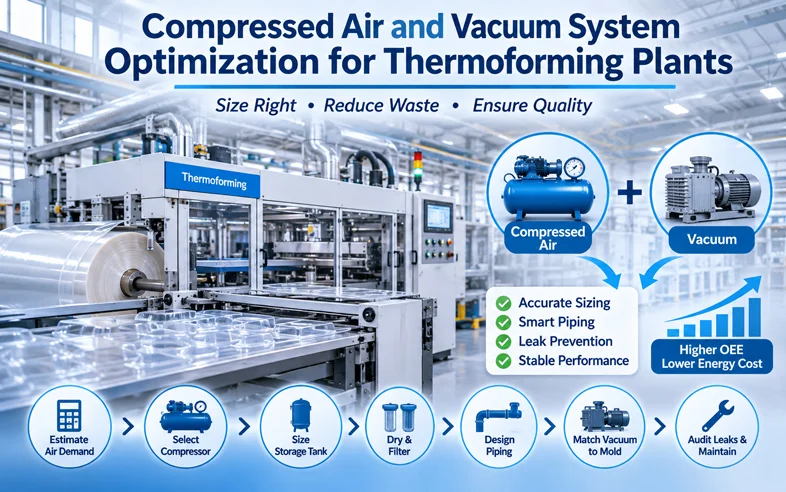
In thermoforming, compressed air and vacuum do three jobs:
Because these functions happen inside the cycle, compressed air and vacuum are part of the process, not just utilities. A pressure drop during forming is not a maintenance inconvenience—it produces scrap. A vacuum system that cannot hold vacuum through the forming cycle produces incomplete parts and slows the cycle.
This is also why compressed air and vacuum appear in the energy optimization discussion: on roll-fed and inline extrusion-thermoforming setups, compressed air generation and heating the sheet can together account for up to 60% of the thermoformer's total energy requirement. Waste in this system is both an energy cost and a quality risk. The thermoforming line OEE and energy optimization playbook covers the energy side in more detail; this article focuses on the system design and maintenance side.
Air consumption depends on machine size, forming area, number of cavities, cycle time, and the specific forming method (positive pressure, vacuum, or both). There is no universal number that applies to every line.
A practical estimation approach:
| Demand Source | What It Depends On | How to Estimate |
|---|---|---|
| Forming air | Forming area, cavity count, pressure setpoint | Cycle consumption per mold × cycles per minute |
| Plug assist and ejection cylinders | Cylinder bore and stroke, cycles per minute | Cylinder volume × cycles per minute |
| Blow-off and cleaning | Number of nozzles, duty cycle | Nozzle flow × open time |
| Leakage allowance | System condition, number of fittings | Typically a percentage added to calculated demand |
The equipment supplier should provide an estimated air consumption figure for the specific machine and mold configuration. Buyers should request this before selecting the compressor, not after.
A common planning mistake is to size the compressor only for the calculated process demand and ignore leakage and future expansion. In practice, leakage can consume a significant share of compressed air output, and a system sized exactly to demand has no margin for leaks, additional molds, or higher production intensity.
Compressor selection follows from air consumption, pressure requirement, and duty cycle.
Key factors:
| Compressor Type | Typical Use Case | Planning Note |
|---|---|---|
| Screw, fixed speed | Stable continuous demand | Efficient at full load; less efficient when demand varies |
| Screw, VSD | Variable demand | Adjusts to demand; can reduce energy use when load varies |
| Reciprocating | Smaller or intermittent demand | Lower initial cost; higher maintenance frequency |
The compressor should be located in a ventilated area with adequate cooling and away from the production floor where possible, to reduce noise and heat load in the workshop.
The storage tank buffers demand fluctuations and allows the compressor to run at a more efficient point. An undersized tank causes frequent compressor cycling and pressure drops during peak forming.
Sizing considerations:
A simple planning rule used in industrial compressed air systems is to size the storage tank for a certain number of seconds of peak demand, with the exact figure depending on compressor control type and demand pattern. Buyers should confirm the recommended tank size with the compressor supplier based on the specific system.
The tank should be fitted with a pressure gauge, drain, and safety valve, and should be included in the maintenance schedule.
Moisture and oil in compressed air affect both the process and the product.
A typical air treatment sequence:
| Stage | Purpose | Planning Note |
|---|---|---|
| Aftercooler | Cools air from the compressor | Reduces moisture load on the dryer |
| Coalescing filter | Removes oil and particles | Protects the dryer and downstream equipment |
| Dryer | Removes moisture | Refrigerated or desiccant depending on dew point requirement |
| Fine filter | Removes remaining particles | Protects the process from contamination |
For food-contact production, the air treatment should be appropriate for the application. Buyers should confirm the required air quality class with the equipment supplier and the food-safety requirements of the destination market.
Piping design affects pressure drop, which affects forming quality and energy use.
Key principles:
| Piping Consideration | Effect | Planning Note |
|---|---|---|
| Pipe diameter | Pressure drop | Size for flow and acceptable pressure loss |
| Bends and fittings | Pressure drop | Minimize unnecessary restrictions |
| Loop layout | Pressure consistency | Ring main reduces variation |
| Isolation valves | Maintenance access | Each branch should have one |
| Drains | Moisture removal | Install at low points and maintain |
The piping layout should be documented so that maintenance can locate branches and isolation points without guesswork.
Vacuum is not a single system specification; it depends on the mold and the product.
Key factors:
| Vacuum Element | What It Affects | Planning Note |
|---|---|---|
| Vacuum level | Forming completeness | Confirm with material and mold design |
| Vacuum volume | Cycle time | Match to mold cavity volume and cycle |
| Vacuum holes | Forming uniformity | Check number, size, and distribution |
| Vacuum pump | Stability and maintenance | Match type to duty and vacuum level |
| Vacuum receiver | Demand buffering | Consider for high-cycle or multi-cavity molds |
A common mistake is to assume that more vacuum always improves forming. In practice, blocked or incorrectly sized vacuum holes can make the system appear weak, and increasing vacuum demand may not fix the problem. The mold should be checked before increasing vacuum.
For mold-related forming issues, the common thermoforming problems and solutions guide covers the diagnostic path in more detail.
Leakage is the most common source of compressed air waste. Industry experience suggests that nearly half the air produced in a typical plastics plant may be wasted through leaks, improper use, and artificial demand. This is not thermoforming-specific, but it indicates the scale.
Leak audit method:
Ongoing maintenance:
| Interval | Task | Why It Matters |
|---|---|---|
| Daily | Drain storage tank and filter bowls | Moisture removal |
| Weekly | Check compressor oil level and pressure | Prevent wear and pressure loss |
| Monthly | Inspect filters and replace if needed | Maintain air quality |
| Quarterly | Leak survey | Identify and fix leaks |
| Annually | Service compressor and dryer | Maintain efficiency and reliability |
Maintenance is not only a reliability measure; it is also an energy measure. A well-maintained system uses less energy to deliver the same air.
Each of these is avoidable with a structured system design and a maintenance schedule.

Air consumption depends on machine size, forming area, number of cavities, cycle time, and forming method. Buyers should request an estimated air consumption figure from the equipment supplier for the specific machine and mold configuration. There is no single number that applies to every line.
The compressor should be sized for peak demand plus a margin for leakage and future use, not average demand. Buyers should request the estimated consumption from the supplier, add a leakage and margin allowance, and confirm with the compressor supplier based on the specific system.
The storage tank should buffer peak demand events and keep pressure drop within the process limit. A common planning rule is to size the tank for a certain number of seconds of peak demand, with the exact figure depending on compressor control type and demand pattern. Buyers should confirm the recommended tank size with the compressor supplier.
In most cases, yes. Moisture in compressed air can cause corrosion, affect vacuum performance, and produce water spots or defects on the product. A dryer and filters are part of a complete air treatment system, especially for food-contact production.
Use an ultrasonic leak detector during production, when the system is at operating pressure. Check fittings, solenoid valves, hoses, cylinder seals, and quick-connect couplings. Log each leak with location and estimated flow, repair in priority order, and re-check after one month.
Blocked or incorrectly sized vacuum holes can make the system appear weak even when the pump is adequate. Check vacuum holes for clogging and confirm that the mold design matches the required vacuum level and volume before increasing pump capacity.
Sizing the compressor only for calculated process demand and ignoring leakage and future expansion. In practice, leakage can consume a significant share of compressed air output, and a system sized exactly to demand has no margin.
Compressed air and vacuum are process utilities, not optional support equipment. A system that is undersized, leaky, or poorly matched to the mold will show up as slow cycles, incomplete forming, and unstable quality. Start with an accurate air consumption estimate, select the compressor for peak demand plus margin, size the storage tank to buffer demand, configure drying and filtration for the process, design the piping for low pressure drop, match the vacuum system to the mold, and audit leaks after commissioning and periodically thereafter.
For lines where air consumption, vacuum performance, or auxiliary equipment configuration is a planning constraint, review the available plastic thermoforming machine and plastic cup making machine configurations, or discuss the system requirements with the Sinoplast engineering team through contact us.
We are a professional plastic machinery provider in China.